H. P. Friedrichs (AC7ZL) Homepage


Radio Room
Building the "Tea Time" Headphone
Introduction
In ever increasing numbers, people seem to be rediscovering the joy of building primitive radio gear, crystal sets in particular. Most published plans require the builder to purchase or salvage constituent parts. Few are aware that all of the necessary components, including earphones, can be constructed by hand.
The basic principle behind an electromagnetic earphone is simple. An audio signal is fed to coil of wire which is wrapped around a metallic core. The audio voltages produce a varying magnetic field in the core. The core is positioned in close proximity to a ferrous diaphragm, such that the variations in magnetic field induce vibratory motion in the diaphragm. The diaphragm, or course, produces the sound. In this article, I'd like to describe the process for building a magnetic earphone using easily obtainable junk.
Construction Details
One must first locate and obtain two metallic
tins with slip-on lids. My tins once contained tea leaves, though
depending upon the part of the world in which you live, such
tins may alternately contain salves, powders, candy, or even paper
clips. Here in the U.S.A, hobby stores sell these types of containers
empty, for decorating, gift, or craft purposes. Henceforth, I'll
refer to one of the tins as "A" and the other as "B."
See photo 1.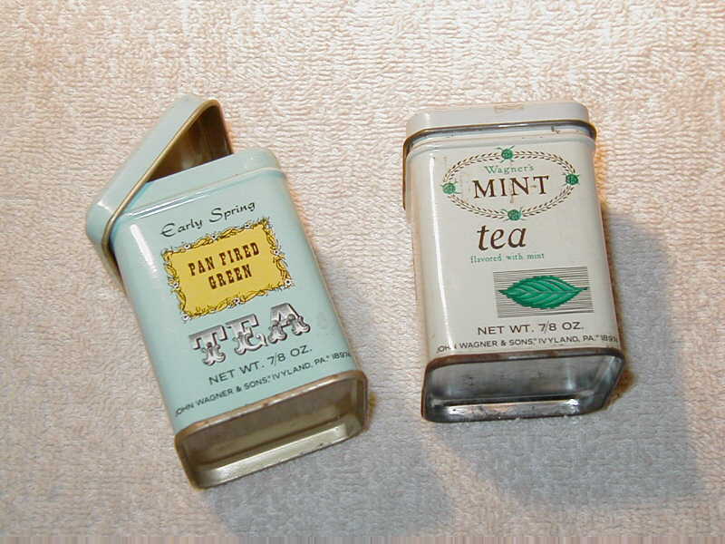
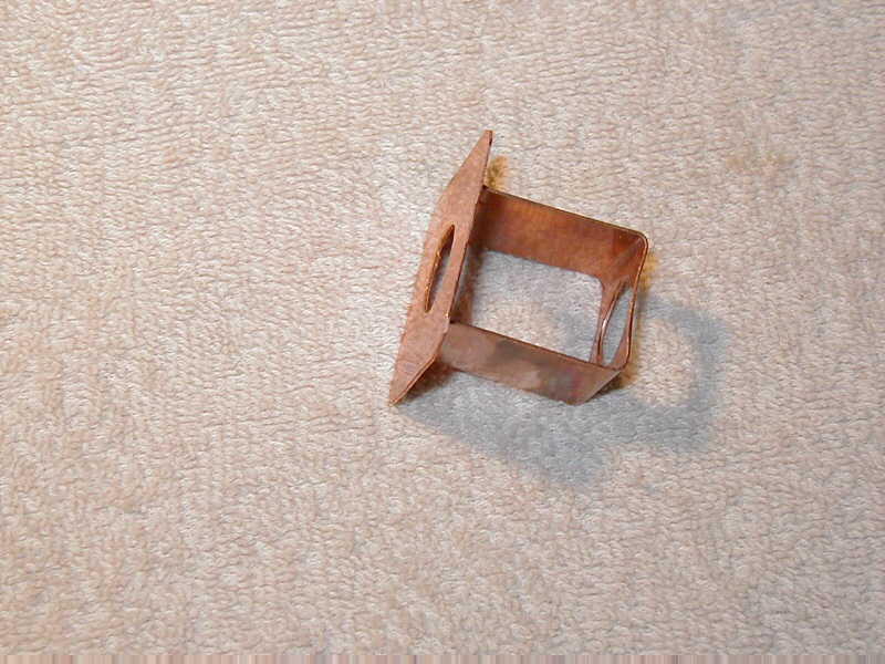
To begin with, the two tins must be modified
so that they will join together. To do this, the lid of tin "B"
must be "skeletonized" as shown in photo 2. 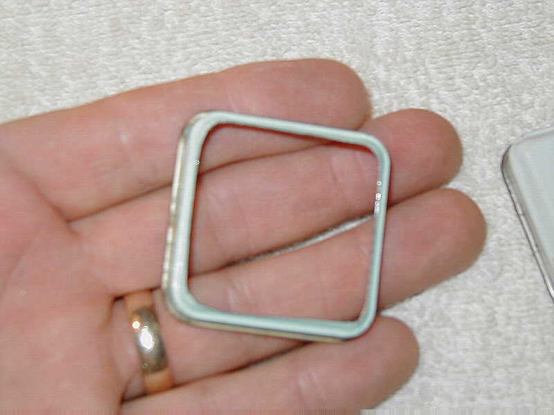
It is then soldered to the rim of the base
of tin "A." This will allow tins "A" and "B"
to be linked together, effectively producing two cavities separated
by a diaphragm (the floor of tin "A"). Before soldering,
use sandpaper on mating surfaces to remove rust or paint. Also,
make sure that nothing impedes the free and natural motion of the
diaphragm. See photo 3.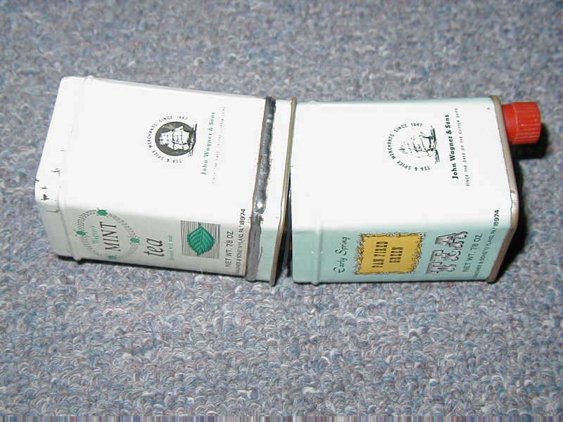
Voice coils for crystal radio work must have
a high impedance. I used a coil salvaged from the ringer of an old
telephone. If you wish, you can try using pre-wound coils salvaged
from small solenoid valves, relays, miniature transformers, or you
can fashion a cardboard bobbin and wind your own. My coil measures
about 3.5 Kohm resistance. See photo 4.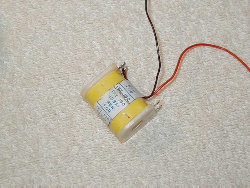
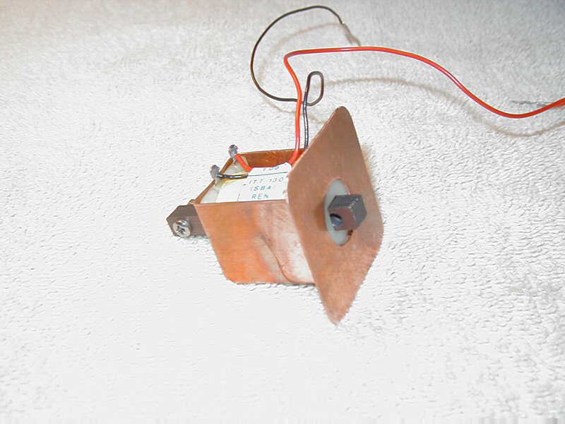
In operation, the coil must be suspended above the diaphragm so that its magnetic field may act upon the diaphragm. This is accomplished through the use of a small square of metal I call the "base plate." The base plate provides a shelf upon which the coil may rest. The plate must be made of a non-magnetic material, and must be bored or punched with a hole to permit the coil's core to pass through it. In my particular case, I made the base plate of copper. I added a U-shaped bracket to secure the coil to the plate. You may elect simply to glue your coil to the base plate and forgo the extra bracketry. Photo 5 shows the completed base plate, and photo 6 shows the plate with the coil installed.
The coil must have a magnetic core. In my
case, I used the laminations that came with the coil. Alternately,
you can use transformer laminations, or even a short bundle soft
iron wire. In any event, the end of the core must be relatively
flat and the core itself must be moveable, such that it can slide
in and out of the coil. Later, this will be necessary in order to
adjust the gap between the core and the diaphragm. The completed
base plate/coil/core assembly may then be lowered into the flange
of lid "B". See photo 7.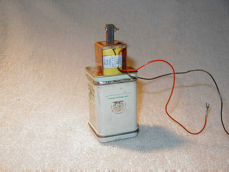
A functional earpiece is made by bolting a
circular jar lid to the lid of tin "A." Once joined together,
I punched a 3/4-inch hole through both of them, and then inserted
a rubber grommet to protect my ear from exposure to the potentially
sharp edges of the metal. Snapped onto tin "A," the earpiece
makes for comfortable listening. See photo 8.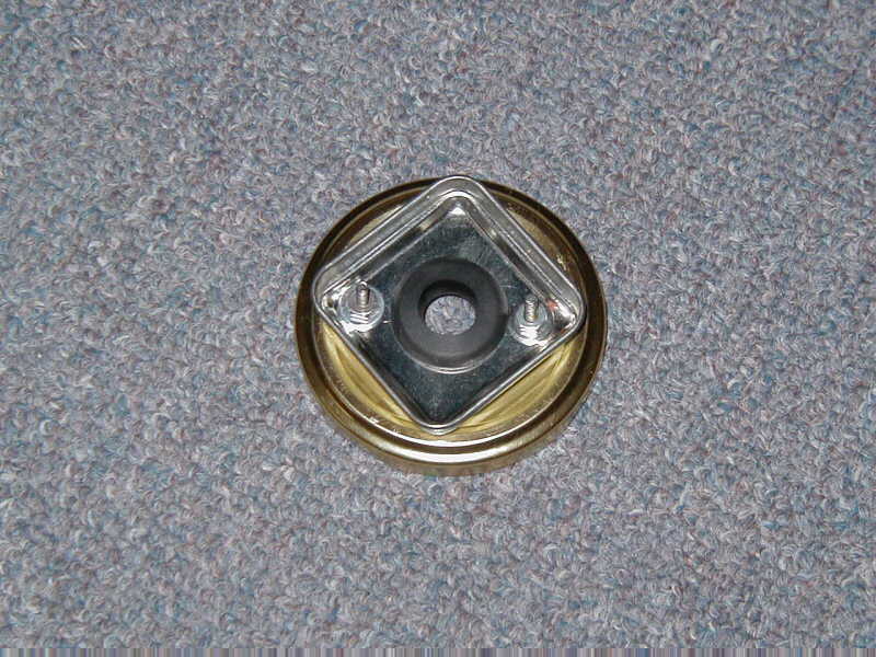
Now wait just a second! What's that silver,
cylindrical object stuck to the core in photo 9?
This is a small alnico magnet that was harvested from a cheap loudspeaker. It is used to provide a magnetic "bias" to the core, which greatly improves its operation. Scrap magnets can be found everywhere...bulletin boards, appliances, speakers, and cabinet catches. In fact, it is best to have a small collection of them from which to chose. Avoid the temptation to use rare earth
magnets...they are actually too powerful.
To finish the assembly process simply snap tin "B" into place, where it will act as a protective housing for the core, coil, and magnet. You will probably have to drill a hole into tin "B," through which a cord may pass. In my case, I installed a pair of binding posts to allow me to make connections to the coil without having to dismantle the earphone.
The earphone requires a final adjustment which take a little patience and finesse. The core must be slid inward or outward such that its face rests a few thousandths of an inch from the surface of the diaphragm. If the gap between the core and diaphragm is too narrow, the bias field in the core will attract the diaphragm and the two will stick together. If the gap is too large, the core will not influence the diaphragm properly, and the volume produced by the headphone will be greatly diminished. There is some interplay between the optimum gap and the strength of the bias magnet, so you may decide, through trial and error, to change your bias magnet to something stronger or weaker.
Photo 10 shows the completed earphone, and
photo 11 shows it in use with one of my experimental "made-from-junk"
crystal sets. 
If you'd like to see plans for the radio pictured above, click here.
Document Revision 1, xx/xx/xx
Document Revision 2, 11/02/2005