H. P. Friedrichs (AC7ZL) Homepage


Radio Room
Building High-Impedance Piezoelectric Headphones
Introduction
One of the hallmarks of the successful crystal radio experimenter, an attribute that dates back to the earliest days of wireless, is the ability to make creative use of materials on hand to construct one's equipment. At the beginning, the need for this skill was driven by the high cost and the relative rarity of the required components. A century of modern electronic production and practice has driven cost to inconsequential levels. However, since many desirable parts have recently become obsolete, the scarcity of certain components is once again providing strong motivation for the do-it-yourselfer.
Essential to any crystal radio equipment is a decent set of headphones. The headphone or earpiece is an energy conversion device, a machine designed to take feeble audio signals created by the radio and convert them back into sound. Recall that the crystal radio is by nature a passive device, one that is not capable of delivering large amounts of audio energy. This means that whatever the nature of our converter, it must be reasonably efficient. This also means that the convertor must be a high-impedance device, that is to say, it must represent a small load to the crystal radio circuitry.
Traditionally, the headphones favored for crystal sets are of the magnetic type. In the magnetic headphone, the audio signal produced by the radio is applied to a coil, wound with thousands of turns of fine wire. The audio signal generates a varying magnetic field in the coil. By placing a metallic diaphragm in proximity to this field, it can be induced to vibrate, producing sound. Antique headsets of this type are still available in sufficient number that they can be purchased through the Internet, though they can be expensive. At least one company produces a new, contemporary version of the classic high-impedance magnetic headset, though they generally don't work as well as the best of the classics. Some experimenters use matching transformers to link their equipment to contemporary, low-impedance headphones. This works too, but again, not as well as the vintage headsets.
A viable option for those interested in procuring suitable headphones is to construct their own. There are a number of books that describe the relevant construction principles involved, including one of my own books, The Voice of the Crystal, which is available through (among several sources) the Xtal Set Society.
Piezoelectric Materials
Many years ago, it was discovered that certain types of crystals would produce an electric current when mechanically deformed. Conversely, an electric current applied to the crystal in the proper way could cause it to move and to deform itself. These behaviors are known collectively as “piezoelectric” effects. Pierre and Jacques Curie performed experiments with piezoelectricity in the 1880's, and identified a number of piezoelectrically active crystals including quartz, topaz, tourmaline, and even crystallized cane sugar. Crystals of sodium potassium tartrate tetrahydrate, more commonly known as Rochelle salt, were eventually fabricated into structures called bimorphs, which were ideal fordriving the diaphragm of an earpiece.
Piezoelectric earpieces satisfy crystal radio requirements for efficiency and high input impedance, and are still available commercially. Piezoelectric headphones have been constructed from scratch, too. At least one member of the Xtal Set Society has produced his own Rochelle salt bimorphs, and I myself have had success with primitive piezo transducers fabricated with crystals extracted from discarded cigarette lighters.
The Piezoelectric Disk
One common piezoelectric device that has not received enough attention among crystal radio experimenters is the piezoelectric disk, or piezo disk. Typical piezo disks are composed of a thin disk of brass upon which is bonded a layer of a ceramic-like material. The ceramic material, composed of barium titanate or similar compounds, exhibits piezoelectric properties. When an electric current is applied to the disk the ceramic material deforms, causing the disk to flex. If an audio signal is applied to the disk, the disk will vibrate and produce sound. Like the earpieces and headphones based on piezo bimorphs, piezo disks work well in headphones and are suitable for use with crystal radio equipment.
In contemporary electric equipment, piezo disks are utilized as annunciators, typically wired to produce beeping or chirping noises. I have salvaged piezo disks from old appliances, alarm equipment, test equipment, and from certain models of desktop telephone where they have been employed as ringers. I have also found them in greeting cards, stuffed toys, and Christmas ornaments of the type that play musical tunes. Worst case, disks are available from surplus electronics dealers for a dollar or less a piece.
Making Piezoelectric Headphones Work
There are two tricks to the successful use of piezo disks as sound-producing elements in a headset. The first is the issue of mounting. Most piezo disks I've seen are glued to the mouth of a ring or cup which supports the disk along its circumference. This allows the disk to wobble in and out, like a diaphragm, when stimulated by an audio signal. Another mounting method I've seen also involves a ring or cup, but one whose diameter is about half that of the disk. Mounted in this way, the disk can wobble in and out near its center, and its periphery can wobble, too. The optimum mounting depends on the disk itself. Conversely, improper mounting will reduce the efficiency of the piezo disk.
The second trick deals with the electrical nature of the disk. We’ve already identified high input impedance as a desirable trait of headphones to be used with crystal radio sets. The input impedance of the piezo disk is extremely high, so high in fact, that to low frequencies it appears to be an open circuit. This can actually become a disadvantage because the detectors in some radio circuits rely on the flow a certain amount of current to functional properly. The audio produced by piezo disks employed under these circumstances may be weak, distorted, or absent entirely. Fortunately, this concern is easily corrected by connecting a resistor in parallel with (across the terminals of) the piezo disk. The value of the resistor is non-critical and can range from thousands of ohms to tens of thousands of ohms. The optimum value depends upon the specific piezo disk and the radio circuit with which the piezo disk will be used.
Building High-Impedance Piezoelectric Headphones From Scrap
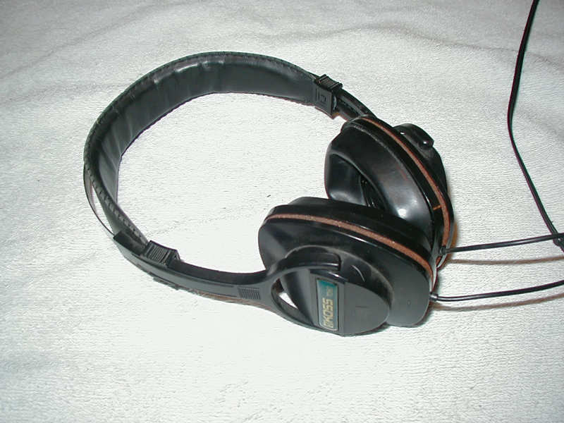
By way of example, I’ve included a few images of a beat-up set of stereo headphones that I chose to retrofit with piezo disks. See figure 1. Most people have headsets of this type in a junk drawer someplace. If not, they are readily available at garage sales and second-hand stores. Useless for anything else, they can be made into both comfortable and effective crystal radio set headphones.
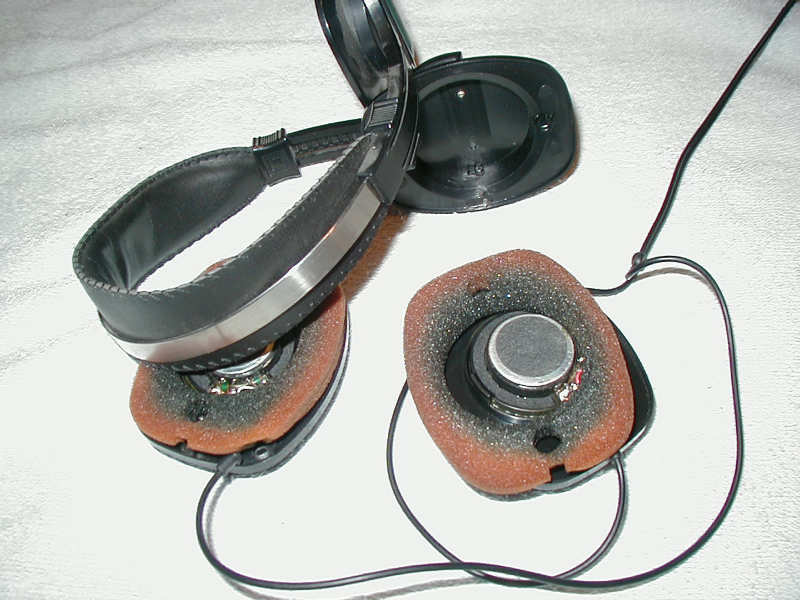
Figure 2 shows the headset partially dismantled. Behind each ear-pad, beneath some foam, lies a tiny loudspeaker. It is necessary to unsolder any wiring connected to the loudspeakers, and then the speakers must be removed.
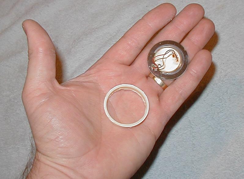
In the palm of my hand in figure 3 is an example of a piezo disk which was removed from the ringer of a junk telephone. Also in my hand, is a shallow plastic cylinder that will serve as the mount for the disk. The diameter of the cylinder was chosen to match the diameter of the disk. I applied a thin bead of model cement to the rim of one end of the cylinder and then pressed the piezo disk into place. (The disk covers one end of the cylinder like the skin on a drum.)
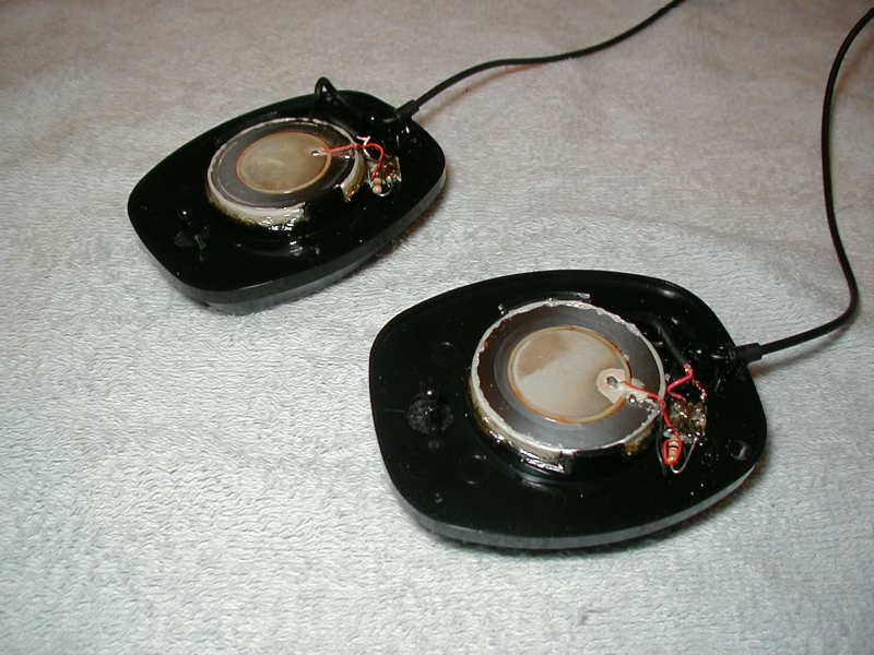
The next step was to install the cylinder/disk assembly into the headphones where the speakers once resided. This was simply a matter of gluing them into place. Figure 4 shows the result. A few comments are in order here. I used as fine a wire as I could find to solder to the disks. Obviously, I didn’t want to attach anything to the disk that might impede its ability to move easily. These fine wires can be seen leaving the 4 o’clock position of disk in the forefront. The wires are soldered to a shunt resistor, which I arbitrarily chose to be 10,000 ohms. This is also where the headphone cable attaches and leaves the earpiece. Because each earpiece has its own 10,000 ohm resistor, when the two earpieces are connected in parallel, the effective impedance becomes 5000 ohms.
The modified headset works well with primitive crystal circuitry and seems to be quite sensitive. While these are no longer “hi fidelity” headphones, the tone quality is good. Both speech and music are clear and intelligible. I have also tried the modified headset with some simple tube circuits and had good results.

Figure 5 shows my assistant, Charlie, demonstrating the proper use of the headset.
(This article was originally prepared for, and appeared in, the newsletter of the Xtal Set Society. Check them out!)
If you'd like to see plans for another easy-to-build homemade headphone, click here.
Document Revision 1, 07/10/2007