H. P. Friedrichs (AC7ZL) Homepage


Radio Room
Building The Hard Drive Morse Key
Introduction
What's the difference between a flower and a weed? Well, even if philosophy is not your strong suit, you've surely heard that one man's trash is another man's treasure. Ultimately it's all about perspective--seeing value in things that others do not. If you're the holder of an amateur radio license, you already know that there are few fraternities more adept at implementing this idea than the ham radio community.
For example, you'd be hard pressed to find a more spectacular embodiment of the trash-to-treasure ethos than the fabrication of homemade Morse keys. Among these designs are some of the most clever and fantastic examples of the re-purposing of materials that you'll ever find.
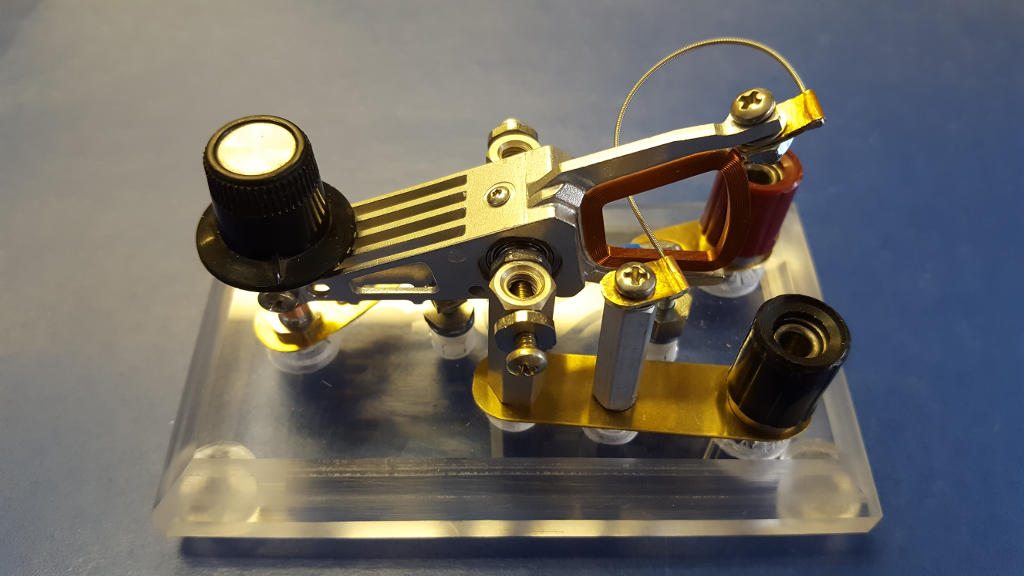
Figure 1: My homebrew hard drive Morse key
I've personally run into several examples of homemade keys over the years, but it's the Internet that makes studying them a real pleasure. Numerous authors have published photos (with build instructions) of their own creations while others have endeavored to accumulate and maintain large photo galleries of other people's work. Several examples can be found in the list of URLs at the end of this article.
Straight keys and paddles have been fabricated from every conceivable kitchen utensil. Keys have been constructed from spoons, forks, butter knives and spatulas. Other favorite "home-brew" materials include metal nail files, hacksaw blades, and clothes pins. Guitar picks, wine corks, upholstery buttons, poker chips, and drawer pulls have been pressed into service as paddles or knobs. Whimsical keys have been fabricated from spark plugs, bulldog clips, cutting boards, office staplers, metal thimbles, and, yes, even Lego (TM).
I can't help it�it offends my sensibilities to throw away parts or materials that might prove "perfect" for some as-yet-to-be-identified future project. That's why I often resort to dismantling unwanted electronics and appliances to strip them of their "treasures" before they end up in the trash can. Pieces and parts end up in boxes, coffee cans, and parts bins. The difference between a ham and a hoarder (my wife would argue they are one and same!) is the execution of that next crucial step where collected junk is actually transformed into something new and useful.
Recently I came into possession of some decommissioned computer hard drives. I dismantled them (as I've done on many prior occasions) with the intent of extracting the powerful rare-earth magnets inside. Having completed that task, I was about to discard the carcasses when I began to fiddle absentmindedly with one of the drives' actuators. It occurred to me that these might form the basis of a nice home-brew straight key design of my own. After a few hours of contemplation, doodles on scrap paper, and fabrication, the end results have exceeded my expectations. You can see the finished product for yourself in Figure 1. Note that every part of this key, with the exception of the rubber feet (which were purchased at the local hardware store), has been fabricated from salvaged materials, scrap, and trash-can pickings.
Interested in building one of your own? There is little to be gained by publishing a "step-by-step" because the whole point of this kind of construction is to make do with what you've got--and it's certain that the junk you've got is not the junk I've got. So instead, I think it best to describe the idea behind this key, its salient features, and why I implemented them the way that I did. This conceptual knowledge (as opposed to a cookbook recipe with parts lists and dimensions) is more likely to be useful in helping you replicate my build.
But first, let's take a quick look at a modern hard drive so you can better appreciate what would inspire this project in the first place.
A Nickel Tour of Your Computer Hard Drive
To those unfamiliar with how they function, one could creatively describe a modern hard drive as the cross between a tape recorder and a phonograph. Like a tape recorder, a hard drive uses a magnetic head to write patterns onto a recording medium. However, instead of magnetic tape, the medium in a hard drive is a rigid disk or platter. The platter, coated with a magnetic compound, is affixed to a rotating spindle that's driven by a motor. An interesting feature of hard drive heads is that they do not actually touch the recording medium while in operation (as tape recorder heads do). Instead they rely upon aerodynamics to glide on a cushion of air a few millionths of an inch above the surface of the platter.
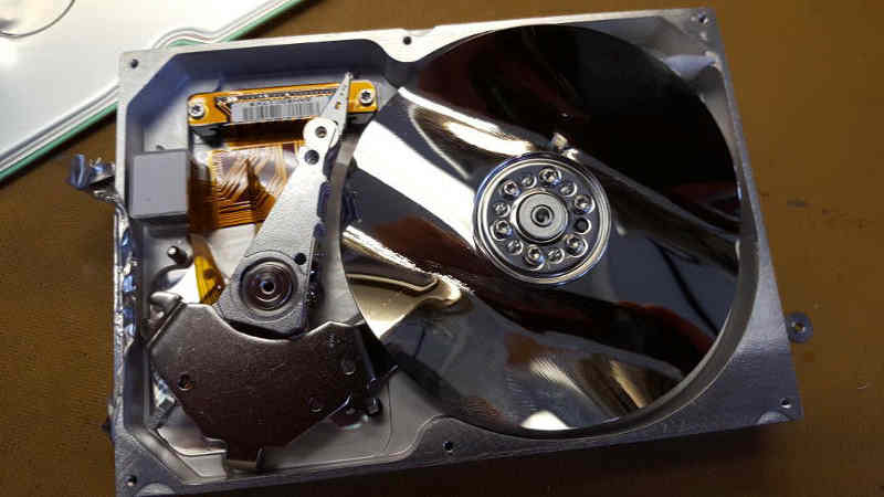
Figure 2: Inside a trashed hard drive
Given a fixed head, the read/write area of a disk would be limited to a single ring prescribed by the head's path over the rotating disk. By making the head movable, a change in the radial position of the head allows data to be recorded all over the disk's surface--organized as a set of multiple concentric rings called "tracks." It's the function of a head actuator to support and move the magnetic head across the face of the disk to the desired track.
This task is not a trivial one. The actuator must provide a stable support for the magnetic head, so as to maintain the infinitesimally tiny air gap between head and disk. At the same time, it must be able to move the head radially across the face of the platter with great speed and precision. At data densities of 100 billion bits per square inch, any flexing, slop or backlash in an actuator would be catastrophic. To complicate matters, no hard drive contains a single head. Since a platter has two sides, the actuator typically supports at least two heads--one for each side of the platter. Some hard drives contain multiple platters stacked with spacers on a common spindle. In this case, an actuator might have to support four, six, or more heads simultaneously.
Over the years, different schemes have been employed to support and move hard drive heads. The most common in use at this time is the so-called "voice coil" actuator.
Physically, the voice coil actuator is a simple lever. At one end of the lever is a set "fingers," spaced like the tines of fork or the teeth of a comb. At the end of each finger is a tiny magnetic read/write head. The fingers intermingle with the stack of rotating platters so as to bring each head into proximity with its corresponding platter surface.
Attached to the other end of the lever is a flat coil of copper wire--the so-called "voice coil"--which is set up to ride between the poles of a powerful magnet. When the coil is energized, magnetic forces are generated which cause the lever to swing, thereby extending or retracting the heads from the platter stack. Needless to say, in order for all of this to work properly, the bearing at the center of this lever must be one of exceptional precision and quality.
At this point, the similarity between a good straight key and a hard drive head actuator should be evident. Both are in essence simple levers. Both benefit from light weight and structural stiffness to allow for rapid, precise, and repeatable motion. Both benefit from quality bearings on which to pivot. So I ask you then: How can anyone throw away a junked hard drive when in its belly lies the makings of a great little Morse key?
Thinking Paper
Every accomplished craftsman and every competent engineer that I have ever known all make use of simple sketches and doodles to flesh out their nascent ideas. An old-timer I once knew scribbled on a ruled pad he called his "thinking paper." I embraced that habit decades ago and never start any project without first consulting my "thinking paper." The more disciplined among us accumulate their chicken-scratches in notebooks or binders, but often a piece of scrap paper or the back of a discarded envelope will do the trick. That's what happened in this case.
Mind you we're not talking about carefully dimensioned drawings or similar formal documentation typically delivered at the conclusion of a project. What I'm talking about is the use of "thinking paper" as a canvas on which to project and exercise one's thoughts while they are still fluid. What parts do I have to account for? How might they be arranged? What is the spatial relationship between part "A" and part "B?" How will they fit and play together?
Lest you think some of the accompanying illustrations crude, their placement here is intentional. They're useful enough to advance the narrative, but what I really wanted to do was to share what my "thinking paper" sometimes looks like.
The Base
The base of my key was made from some 1/2-inch thick polycarbonate scrap. It measures 2-1/2 x 4-1/4 inches. The top edge was heavily beveled with a sander. All fasteners entering from the bottom are countersunk. A photo of the bottom of the base can be see in Figure 3.
Because the key operates so smoothly, the comparatively light weight of the base is not really a problem--particularly since I added four silicone rubber feet to prevent skidding. Still, you might consider a different base material for your own key, or perhaps the addition of some mounting holes that would allow the key to be attached to a desktop or a slab of something heavier.
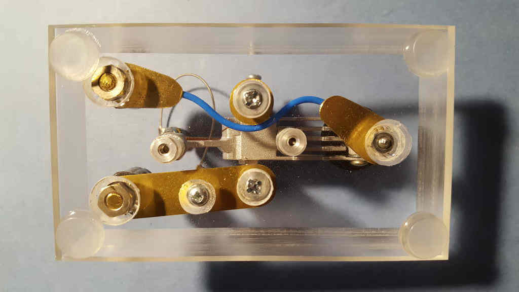
Figure 3: Underside of the Morse key's base
Trunnions
The lever of a typical Morse (straight) key has a set of trunnions. What's a trunnion? The word has a military origin and is associated with artillery. If you've ever seen photos of an antique cannon--I'm talking "Civil War" or "Napoleon" here--you've no doubt noticed the two cylindrical horns that project from the sides of the barrel. These are its trunnions. They're used to anchor the cannon to its carriage and to provide a pivot by which the elevation of the gun can be adjusted. Likewise, Morse key trunnions secure the key lever to its base and provide a pivot by which it can be moved up and down.
The trunnions of a typical Morse key fit into bearings held by a pair of bearing supports. A hard drive actuator has no trunnions because its bearing resides inside of the actuator itself. The support structure for the lever of my key, then, is sort of the inverse of what you'd normally find.
If you refer to the photo in Figure 1 and my "thinking paper" image in Figure 4, you'll see that the supports for the key lever are nothing more than a pair of threaded aluminum hex standoffs. The standoffs are secured to the base with 8-32 screws and #8 flat washers.
To provide bearing supports, I drilled crossway through each standoff near the top. A 4-40 screw passes through the support and threads into the bearing in the actuator. A pair of nuts allow the bearing screw to be locked so that use of the key won't cause it to work its way out.
.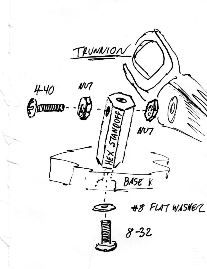
Figure 4: An example of "thinking paper." Details of the trunnions
Surprise #1
As simple and straightforward as my trunnion supports seem, this was the point where I experienced the first surprise of this project. Let me explain:
When I first conceived of assembling my key, I tested a handful of screws from my junk box to see which would thread successfully into the actuator bearing. A 4-40 screw fit nicely. I naively assumed that the threads at both ends of the bearing would be the same. They were not. In fact, one side was 4-40, the other was a metric thread of some type!
You can imagine this created a problem for me. I did not have any metric nuts nor screws of sufficient length. The bore of the bearing was hardened, so it was not practical to drill it out and tap new threads into it.
I resolved the problem this way: On the left side of the key, the 4-40 bearing screw threads into the bearing as previously illustrated/described. On the right side of the key, the 4-40 screw was sharpened into an acute point that projects into the metric-threaded hole. Figure 5 illustrates this idea.
Between the two trunnion screws, the actuator is held securely, but teeters smoothly on its bearing with no signs of slop or side-to-side play.
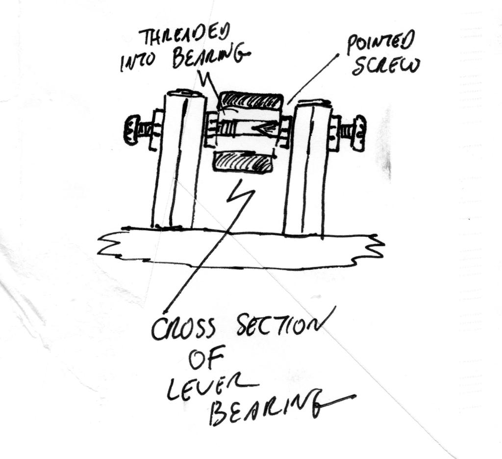
Figure 5: Dealing with mis-matched mounting holes
Preparing the Key Lever
To serve as a proper Morse key lever, I had to devise some means for attaching a knob to the head-end of the actuator. I also needed to find some way to mount a switch contact. Happily, I found a way to do both with the simple assembly shown in Figure 6.
First, I needed to modify the actuator. Mine featured five fingers, complete with read/write heads. I began by carefully pulling off the heads with a pair of needle-nose pliers. Then, using a pair of side-cutters, I shortened the three middle fingers. This allowed me to install a small hex standoff, about 7/16 inch in length, between the remaining (outer) fingers. The standoff was secured with short 4-40 screws and some lock washers.
Next, I drilled a hole crossway through the center of the standoff. The contact screw (I'll describe this in greater detail in just a moment) was inserted through the hole from the bottom and secured at the top with another hex standoff. The latter was then inserted (and glued) into the bore of a plastic knob. Additional nuts were fitted, as necessary, to space everything properly. See Figure 7.
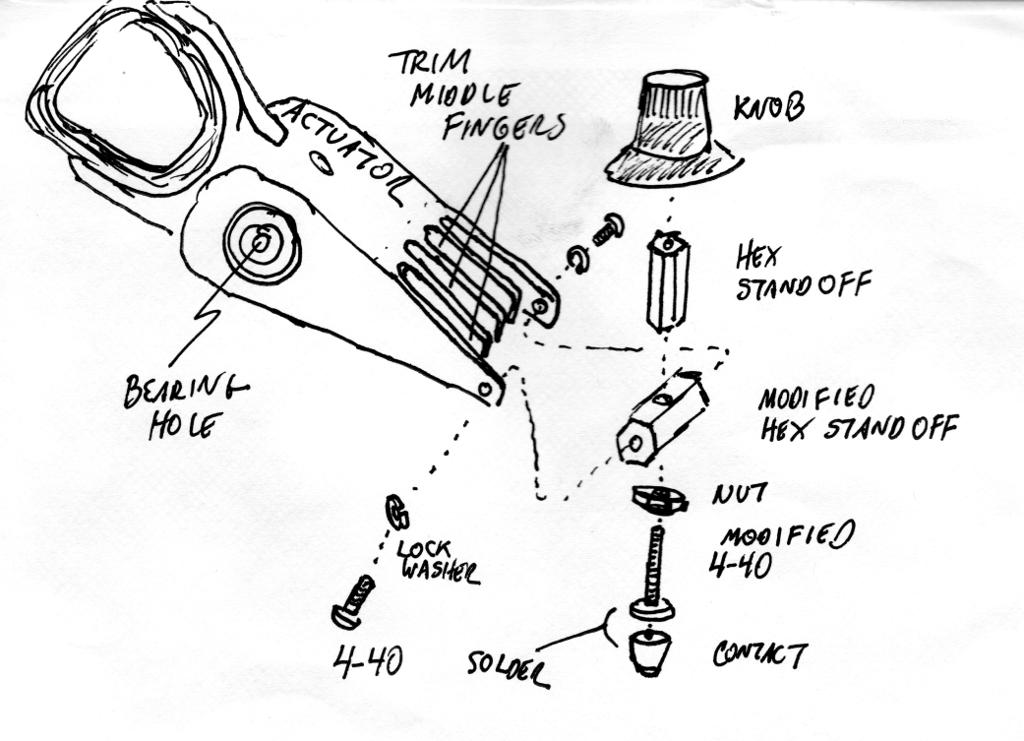
Figure 6: A plan for modifying the hard drive's head actuator
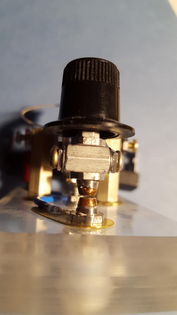
Figure 7: The front end of the completed key lever
Contacts
Ultimately, a Morse key is nothing more than a momentary-contact switch. To close a circuit, all a switch needs to do is to bring two conducting surfaces into contact. Simple... or so it would seem. In fact, designing a reliable, high-quality switch is notoriously difficult.
Part of the problem stems from the chemically active nature of most metals. Exposure to air and moisture invariably encourages the growth of oxides, corrosion, and other surface films that can result in poor contact and poor electrical conductivity. Even under the best of circumstances, mechanical switches are subject to chatter and "contact bounce." This is a phenomenon where a single physical closure of a pair of contacts can actually result in a rapid and chaotic series of electrical "makes" and "breaks" before a stable connection is finally achieved.
Switch manufacturers, who have researched and understand the physics behind these problems, have gone to great lengths to develop alloys from which superior contacts can be made. So, rather than reinvent the wheel, I chose to defer to their expertise. My contacts were harvested from a discarded relay. See Figure 8.
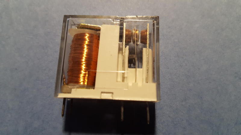
Figure 8: A discarded relay. Note the switch contacts at the upper right
Relay contacts are usually riveted in place, but they can be extracted through the clever application of a drill bit, pliers, or a small chisel. Note that my Morse key requires two such contacts, one of which is attached to the key lever and one which is anchored to the key's base.
To make salvaged contacts useful, they need to be attached to a threaded stem. I made my stems from 4-40 screws. The screws were chucked in a hand drill and spun while the heads were dressed with a bastard file. The object here was to eliminate the screw slots and render the head perfectly flat.
When the stems were complete, they were each topped with a salvaged contact and then the contacts were soldered to the stems to hold them in place. See Figure 9.
Needless to say, the completed lower contact is mounted in the base of the key and positioned directly beneath the upper contact in the key lever. See Figure 10.
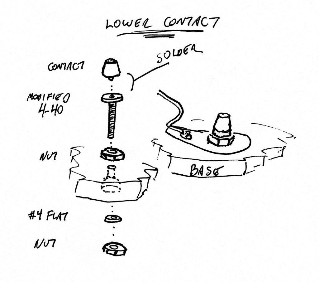
Figure 9: Plan for a contact assembly and the installation of a contact assembly into the base
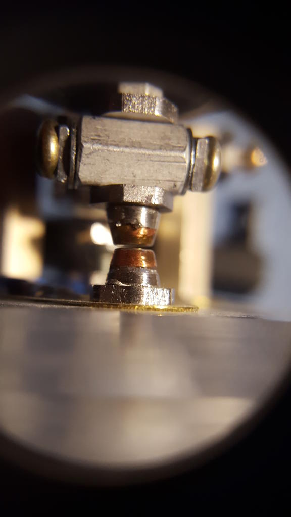
Figure 10: Close-up of the upper and lower contacts, installed
Magnetic "Return Spring"
When a Morse key is depressed, the switch contacts close. When the key is released, the contacts should open of their own accord. This implies the use of a spring of some kind to return the key lever to its rest position. Typical straight keys employ small compression springs for this purpose. For this key design, I thought it might be interesting to dispense with coil springs and instead make use of the repulsive force created between like poles in a pair of magnets.
Defective CDROM and DVD drives, like computer hard drives, contain useful parts that are best salvaged before they are thrown away. Among these are a set of tiny rare-earth magnets used as part of the focusing mechanism in the drive's optical head. Just beneath the optical head's lens is a set of coils and an armature on which tiny magnets are glued. The magnets are typically square or rectangular in shape, and are about the size of an aspirin tablet. Being rare-earth magnets, they are disproportionately strong, which makes them useful for a variety of purposes. A bit of gentle bending of the armature with a pair of needle-nose pliers is usually enough to fracture the glue and set the magnets free. Be cautious if applying force directly to the magnets themselves, as they tend to be brittle.
Two magnets are required for my Morse key. One magnet was glued to the underside of the key lever with a dab of two-part epoxy. The second magnet was glued to the head of a 4-40 screw. The screw was first chucked in a drill and its head was flattened in the same fashion as the contact stems were. The magnet on the stem, of course, is oriented so as to repel the magnet glued to the key lever.
I drilled a small hole in the base of the key and located it so that the magnet on its stem rests directly beneath the magnet glued to the key lever. A 1/4-inch standoff pressed into the base from the underside acts as a threaded insert, allowing me to adjust the gap (and therefore the amount of "spring") between the two magnets. A nut and washer on the top side of the base allows for adjustments to be locked. See Figures 11 and 12.
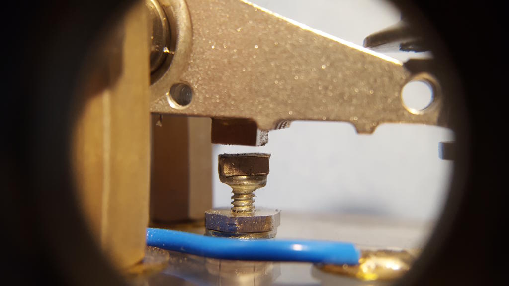
Figure 11: The magnetic "return spring"
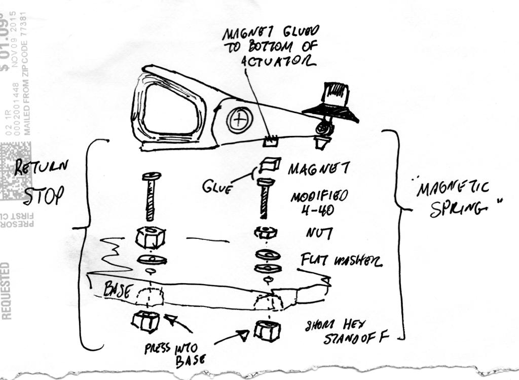
Figure 12: More "thinking paper." Details of the magnetic spring and return stop
Return Stop
One characteristics that affects the "feel" of a key is the spacing between the key contacts. If the gap between contacts is wide, then a lot of key travel is required to close them. This represents extra effort and fatigue on the part of the operator. On the other hand, if the contacts are too close together, the tactile feedback normally produced by a decisive contact closure is missing. Some operators may not like that. The best circumstance is if the contact gap can be adjusted. In my key, this adjustability is provided by a return stop screw.
The return stop screw is a 4-40 screw, whose head has been flattened like a contact stem. It is attached to the base of the key and is located beneath the key lever at its rear. At rest, the magnetic "spring" forces the key lever upward. This causes the tail end of the lever to move downward until it comes to rest on the head of the return stop screw.
A 1/4-inch standoff pressed into the base from the underside acts as a threaded insert, allowing the height of the return stop screw to be varied. Raising the return stop screw closes the contact gap at the front of the key. Lowering the screw increases the gap. A nut and washer on the top side of the base allows for return stop adjustments to be locked. See Figures 12 and 13.
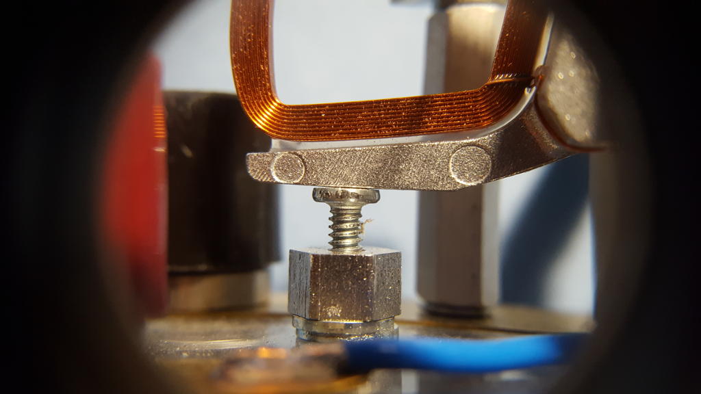
Figure 13: The close-up of the return stop screw
Surprise #2
Conductive pads made from brass shim stock and a short piece of wire were fabricated to carry current in and out of the key. They were terminated at a set of banana jacks at the rear of the key.
With the key depressed, I had planned for current to enter the left (red) banana jack, pass through the wire to the lower key contact, from the lower contact to the upper contact in the key lever, through the key lever to the right trunnion, and from the trunnion to the right (black) banana jack. Simple, right?
Surprise! It didn't work! With the key depressed, the resistance measured between the banana jacks was more than 1000 ohms! I cobbled together a second key lever from another hard drive actuator and installed it. This time, the closed key didn't show any continuity at all! What the heck was going on?
A quick check with my multimeter revealed that the fault lay between the key lever and the trunnion. In other words, current didn't seem to want to flow through the actuator bearing. I had presumed that it would (I have a Japanese straight key where key current is passed through a set of ball bearings in one of the trunnions). So why didn't it work in this case?
The truth is I don't know. My guess is that the bearings in a hard drive head actuator are not run-of-the-mill. If the balls in the bearing are not metal but ceramic, for example, or if the balls are metal but the races are ceramic, then there would be no conductive path from the inner to outer race. That left me wondering how I might salvage my key design.
In the end, I literally "worked around" the problem by providing a current path that bypasses the bearing entirely. This is evident in Figure 14 as a thin, spring-like wire that appears at the top rear of the key lever. That wire is in fact a piece of "D" string from an electric guitar. It provides a flexible electrical path from the right-hand banana jack directly to the key lever.
The guitar string was terminated at each end with little metal tabs fashioned from brass shim stock. The tabs were soldered to the ends of the guitar string. They were then drilled to clear 4-40 screws. One tab was fastened to a preexisting hole in the tail of the key lever using a screw, nut, and lock washer. This can be seen in Figure 15. The guitar string threads through the voice coil at the rear of the key and terminates at the top of hex standoff using a 4-40 screw.
The action of the key's movement on the string is torsional and can't amount to more than a degree or two of twist. A tiny influence like that on a material as strong and elastic as music wire will never cause it to wear out or break. Conversely, the effect of the guitar string on the feel of the key lever is undetectable.
The good news is this: The closed-contact resistance of the key with the guitar string bypass in place measures a scant few tenths of an ohm--commensurate with the intrinsic resistance of my meter probes themselves.
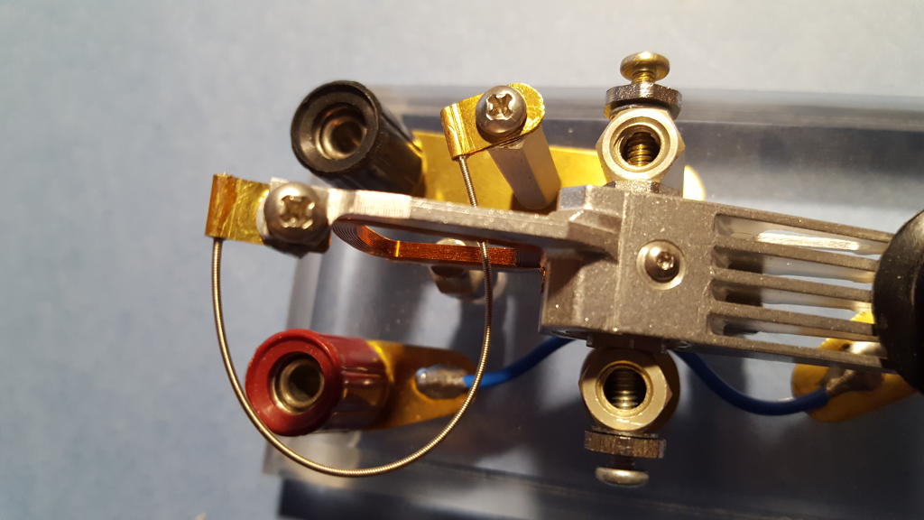
Figure 14: A guitar string corrects the bearing's conductivity problem
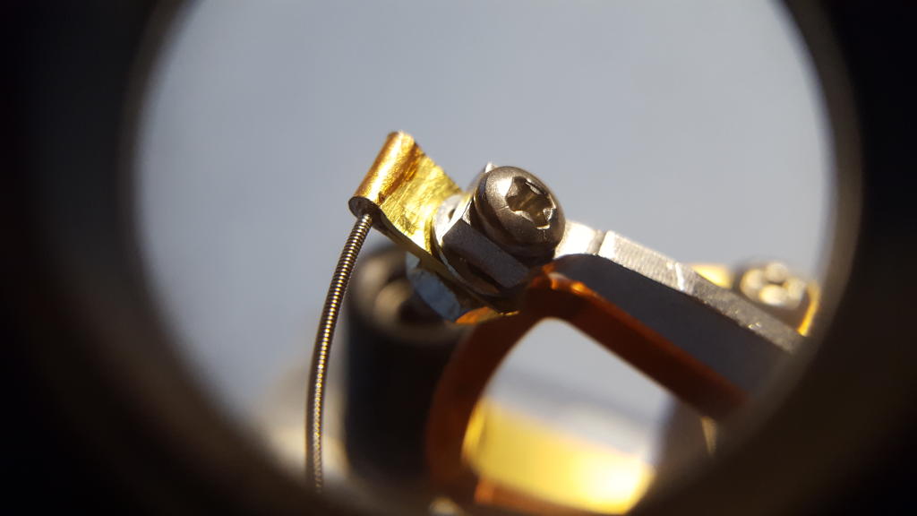
Figure 15: Terminating the guitar string with a brass shim stock tab
Conclusion
The full measure of a Morse key's worth is best determined by an operator with significantly greater skills than I have. That said, I think there are several justifiable (if subjective) comments I could make.
For my tastes, this key plays well. Owing to the exceptionally high quality of the bearing, there is no slop or backlash in the motion of the lever. The action is smooth and nearly effortless. The magnets, used in lieu of a return spring in this design, have a nice feel--they generate an appropriate return force but are suitably compliant without feeling mushy. Contact closure is crisp and assertive, without chatter or bounce. Best of all, there is sufficient adjustability baked into this design to account for variety in personal preference.
My key may not rank with some high-end Begali, but I judge it to be as good as my J-38, my old Bunnell, and my Russian "spy" key. And I'd happily put it head-to-head against any home-brew key made from kitchen utensils!
Finally, it is worth nothing that I have successfully built not one but two keys of this type, which speaks to the reproducibility of the design.
The next time one of your hard drives goes south or you see a dead computer sitting on the curb on garbage day, why not consider building your own version of my hard drive Morse key?
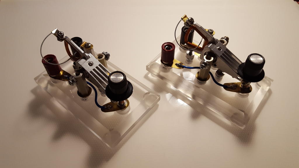
Figure 16: Meet the Morse key sisters... Virtually identical twins
URLs for Other Home-brew Morse Keys
|
|
|
AR15.COM: Paper clip key |
|
|
|
Ham Projects: Table knife bug |
|
http://hamprojects.blogspot.com/2013/12/homebrew-cw-paddle-cost-0.html |
|
|
|
Ham Radio Ireland: Home-brew paddle key |
|
http://hamradioireland.blogspot.com/2010/05/homebrew-single-paddle-cw-key.html |
|
|
|
Hosung's Blog: Home-brew paddle key |
|
http://hosungw.blogspot.com/2015/05/homebrew-morse-code-paddle-key.html |
|
|
|
I6QON: Assorted keys including home-brew |
|
|
|
K5BCQ: Assorted keys including home-brew |
|
|
|
LA6AKA: Home-brew paddle key |
|
|
|
Morse Laboratory: Nearly 200 images of home-brew keys |
|
|
|
OH6DC: Home-brew bug |
|
|
|
RISC-A-DAY: Poor man's paddle |
|
https://risc-a-day.blogspot.com/2015/05/poor-mans-paddle-cw-key.html |
|
|
|
VK1SV: Bunnings Special home-brew key |
|
|
|
W1TP: Assorted keys including home-brew |
|
|
|
W6DAS: Assorted keys including home-brew |
|
|
|
WA5BDU: Assorted keys including home-brew |
|
|
|
WB9LPU: Home-brew keys |
|
https://sites.google.com/site/wb9lpu/homebrewstraightkeysbywb9lpu |
|
|
|
WB9LPU: Two straight keys |
|
|
|
WB9LPU: A simple straight key |
|
|
|
WB9LPU: A Marconi style key |
|
|
|
WR Smith: Keys by WR Smith |
|
|
Document Pilot, 11/28/2016
Revised 05/12/2021