H. P. Friedrichs (AC7ZL) Homepage


Radio Room
Building the CDROM Radio
Introduction
If you've studied the subject of crystal radio for any length of time, you're already aware that these instruments appear in an endless variety. The diversity found in vintage commercial sets is intriguing enough, though I have a special appreciation for homebrew sets and the unusual materials that one tends to find in their construction.
I submit that there is no better place to rummage for radio materials than the nearest waste can. If you've got the right eye, there's always something that can be pressed into service as part of your next project. Empty toilet paper tubes and the venerable Quaker Oats (TM) box are timeless examples of ingenious recycling. I, myself, have built radio components from shoe polish tins, cigarette lighter parts, bits of scrap metal, transformer windings, and similar junk. In this article, I'd like to describe the construction of a set based on some contemporary refuse that you may not have considered.
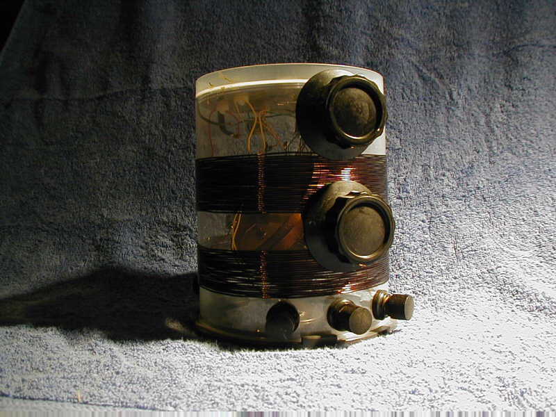
Most home computers systems now feature CD-ROM drives capable of writing to, or "burning" CD-ROM blanks. The blanks are usually purchased stacked on spindles and housed in cylindrical plastic containers. The radio described in this article is based on an empty CD-ROM container, two blank CD-ROMS, and a handful of other odds and ends. The circuitry is simple, but the set performs well. The tuner portion consists entirely of home-built parts (no variable capacitor is required) yet it can be tweaked to sweep the entire A.M. band. Detection can be accomplished either with an internal diode or with an external detector of your choice. Figure 1 shows the completed radio.
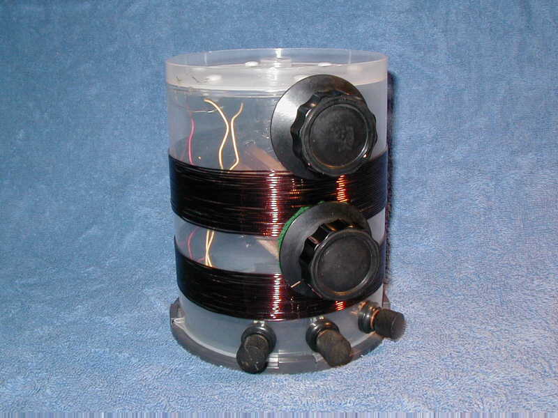
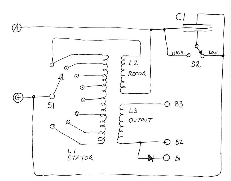
A glance at the schematic in figure 2 suggests that the CD-ROM radio can be broken up into four subassemblies. First, there is the tuning capacitor C1, followed by a stator coil L1, a rotor coil L2, and finally, and output coil L3, all of which are mounted in or on the CD-ROM container.
The Tuning Capacitor
Tuning capacitor C1 is a sandwich composed of three metal disks separated by two CD-ROMS. The CD-ROMS, which function as the capacitor's dielectric, must be carefully chosen. Retail packages of CD-ROMS usually contain a couple of clear, nonfunctional CD's that are placed at the ends of the stack to protect the product from scratches. These are the ones to look for. (I've heard that "burned" CD-ROMS can be stripped down to clear plastic by a prolonged soak in bleach.) I cut my disks from brass shim stock, though you could probably use copper foil as well.
The C1 sandwich is both compressed and anchored to the inside of the top of the CD-ROM container using six 6-32 nylon screws and nuts. Because the screws must penetrate the sandwich, they must be non-metallic to avoid creating a short circuit. Before assembling and mounting C1, a thin wire should be soldered to each of the three plates to provide a connection point.
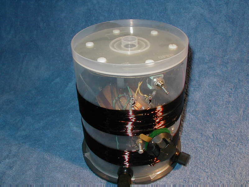
Switch S2 is a single-pole, double-throw toggle switch. In the "high" position, the middle and bottom plates of the capacitor are shorted together. This effectively eliminates the bottom plate as a contributor to the sandwich's total capacitance. When the switch is thrown to the "low" position, the bottom plate is instead connected to the top plate. In this configuration, the tuning capacitance is doubled. Figure 3 shows the both the tuning capacitor and S2.
Stator Coil
The stator coil, L1, is wound on the outside of the CD-ROM container using 18 gauge enameled magnet wire. L1 begins about an inch above the bottom edge of the CD-ROM container, and progresses upward 20 turns. I skipped 3/4 inch, and then laid down 15 more turns. To wind L1, I used a heated needle to burn two tiny holes through the wall of the CD-ROM container. I threaded the end of the magnet wire through these holes to provide an anchor and then began winding in a clockwise direction, as viewed from the bottom of the container.
L1 is a tapped coil. After every 5th turn, I burned two more holes into the container. The wire was threaded through one hole into the interior of the container, twisted to form a 1/4-inch loop, and then threaded back out. The winding of L1 then continued. When all 35 turns were in place, the free end of the wire was anchored by looping it through a couple more needle-holes.
Switch S1 is a single-pole, 12-position rotary switch. Since the ends of coil L1 and its taps only amount to 8 positions, the 12-position switch has 4 unoccupied terminals. These may be useful if you end up adding more turns to L1. I had a nice 2-inch Bakelite knob in my junk box, which I attached to S1's shaft.
Rotor Coil
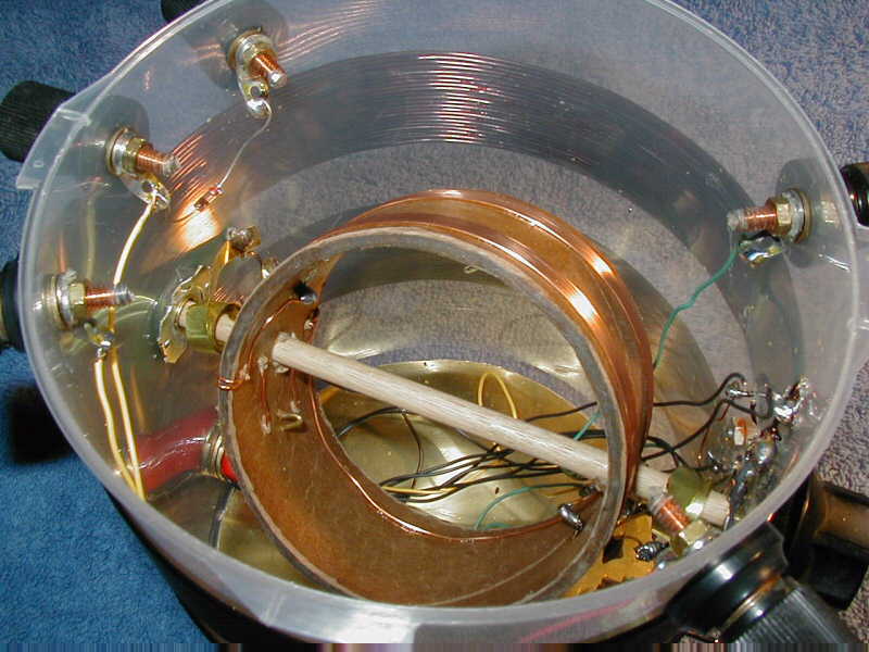
Rotor coil L2 is based upon a cardboard form, 3 inches in diameter and 1-1/2 inches in length. It was cut from a standard cardboard mailing tube, and then soaked in polyurethane to stabilize and strengthen it. I wound L2 with 20 turns of 18-gauge enameled magnet wire. The coil is laid out as two 10-turn banks, separated by a 3/4-inch gap. The coil is anchored and terminated in needle holes where are burned through the cardboard form. The coil form is also pierced at two points to accept a 1/4-inch hardwood dowel that will function as an axle. See figure 4.
When installed in the radio, coil L2 is suspended and rotates within the bore of L1. While it would be simple enough to drill two holes into the walls of the CD-ROM container to support L2's axle, that approach is crude, at best. A better idea is to locate two old potentiometers (volume controls) and take them apart. If you're careful, you can salvage the threaded brass bushing in which the potentiometer's shaft rotates. These make excellent bearings for L2's axle, and will allow smooth, precise rotation.
The schematic in figure 2 shows the rotor coil wired in series with the stator coil. This raises a question as to how one can make an electrical connection to a rotating coil. The simple answer is to use two pieces of thin, stranded wire (never throw out a dead computer mouse without saving the wire). The problem with wire is that repeated flexing will eventually break it. Instead of wires, I used narrow ribbons of brass shim stock, wound into spirals around L2's axle, One spiral is coiled in a clockwise direction, the other in a counter-clockwise direction. As L2 is rotated, one ribbon winds, the other unwinds, but in either case, the flexing is never sufficient to cause the ribbons to break. One of the ribbons can been seen at the far left of the rotor axle in figure 4.
The ends of L2's shaft were fitted with old Bakelite knobs, more treasures from my junk box. A 2-inch knob was affixed to the front of the radio, a smaller 1-inch knob was used on the back. The large knob makes rotor adjustment convenient. The smaller knob helps keep the shaft from sliding back and forth in the bearings, thereby keeping the rotor centered within L1. If you find that the rotor turns too easily, and won't hold its position once adjusted, cut out some washers from felt and place them between the knobs and the wall of the CD-ROM container. These will produce a gentle friction to keep the rotor in any position that you set it.
Output Coil
The output coil L3 is similar in nature to the stator coil. It's wound on the exterior of the CD-ROM container and consists of 10 turns of 18 gauge magnet wire positioned directly above L2. The terminals of L3 are wired to binding posts B2 and B3. A 1N34 germanium diode (or similar) links binding posts B1 and B2.
Miscellaneous
External connections are made to the radio with binding posts. In my case, I had some black Bakelite binding posts salvaged from some old electronics. Fahnstock clips would work fine, as would 5-way binding posts of the type manufactured by Pomona. If you want, you could also use 6-32 screws with wing nuts.
The plastic from which CD-ROM containers are made (PP) is a strange material. It seems flexible and compliant, yet it's actually quite brittle. Be very careful drilling holes through it, because if the drill bit should snag, the container will virtually split in half. I'd suggest that you melt any holes that you need using a heated wire or a hot Exacto (TM) blade. Likewise, be very careful when soldering to your coil taps. If you aren't quick and precise, the wire will heat the point where it will simply cut through the wall of the container.
The CD-ROM container is makes a nice, stable, coil form. Unlike cardboard or wood, it won't shrink with changes in humidity. However, it doesn't hurt to firm up your coil windings by "doping" them together. Clear nail polish is nearly invisible, dries quickly, and will bond the coil windings together into a nice, stable, mass.
To be useable, the rotor coil should turn about 360 degrees. Turning it farther offers no advantages, and may even result in damage to the brass spirals described above. To prevent this, I attached a brass "finger" to the rotor shaft at the rear of the radio, and installed a small bolt which functions as a mechanical stop. See figure 3.
Operating the CD-ROM Radio
As is the case with all crystal sets, receiver performance is governed by the quality of the antenna and ground you provide. These are connected to terminals A and G, respectively. Also as usual, this set works best driving high-impedance loads. A 2000 ohm headset or a crystal earpiece with a 47k-ohm shunt, connected between B1 and B3, works just fine. Tuning the set involves playing with the settings of switch S2, S1, and the angular position of the rotor coil L2.
S2 controls the value of the tuning capacitance C1. Use the "low" position for stations at the low end of the broadcast band. Use the "high" position for higher frequencies.
The inductance of the stator coil L1 is determined, in part, by the position of the tap switch S1. The more turns selected, the larger the total inductance of L1. The larger the inductance, the lower the frequency tuned by the radio set.
As S1 snaps from position to position, the inductance of L1 changes in discrete steps. What if the station you're interested in lies somewhere in between? This is where the rotor coil L2 comes into play.
L2 lies within the bore of L1, and the two coils are connected in series. This means that the magnetic fields associated with these two coils can interact. If L2 is positioned such that its field enhances the field produced by L1, The total inductance of the L1-L2 pair is increased. If L2 is flipped 180 degrees such that its field opposed the field of L1, the overall inductance is reduced. The adjustment of the angular position of L2 allows for an infinite variation in the inductance of the L1-L2 pair. Such a configuration was once commonplace in early receivers, and was referred to as a "variometer."
The set's internal diode is quite sensitive. With a test antenna composed of 25 feet of bell wire and ground wire terminated on a nearby switch plate, I was able to tune 6 or 7 stations. The various controls are highly interactive and their effects overlap, so it's possible to tune the same station through different combinations of adjustments. One combination, however, always results in the greatest volume and sharpest tuning.
If you'd prefer to use an external detector, wire it in series with your headphones and connect them to terminals B2 and B3. On a fluke, I shunted B2 and B3 with common, red LED. With the set tuned to a local public radio station, I could generate enough voltage to actually light it!
If you'd like to see plans for a nifty home made earpiece to go with this radio, click here.
(This article was originally prepared for, and appeared in, the newsletter of the Xtal Set Society. Check them out!)
Document Revision 1, xx/xx/xx
Document Revision 2, 11/02/2005